Pipeline
Pipeline stages and phases
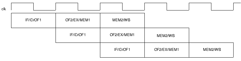
Currently, the SpartanMC uses a three stage pipeline driven by one
clock signals. IF, ID and OF1 are combined to form the first stage,
OF2, EX and MEM1 form the second stage and MEM2 and WB the third stage.
| IF | - | Instruction Fetch |
| ID | - | Instruction Decode |
| OF | - | Operand Fetch |
| EX | - | Execute Instruction |
| MEM | - | READ/WRITE Memory |
| WB | - | Write Back |
Block diagram of the SpartanMC pipeline
The SpartanMC has no separate memory for data and
instructions. Instead it uses dedicated ports for instructions
and data implemented via FPGA dual port BlockRAMs. This partition
allows a modified Harvard achitecture. The data memory is organized
in 2k x 9 bit configuration, using two BlockRAMs in parallel which
simplifies writing on 9 bit wide data. An arbitray number of those
pairs can be used to form the main memory of the system.
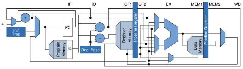
The classic SpartanMC pipeline used phase splitting to read or
write the register memory. In the first phase the register is
used to store the result form the WB stage (cf. lower port of
register memory). In the second phase it is used to read the
operands (cf. upper two ports of register memory). The memory
addresses are computed by the adder of the ALU. In order to relax
the timing of the IF/ID/OF stage the current pipeline uses a true
three port memory to avoid the phase splitting.
(In the diagram there are several things not shown e.g. write access
to data memory or the special function registers.)